Grand Central Terminal
Interlockings
The interlocking machines at Grand Central were installed and documented in the period from 1913 to 1915 and maintained in use until the early 1990s. Each machine has a row of levers with “pistol grip” handles. A lever pushed in toward the cabinet is in the Normal position; one pulled all the way out is Reverse. These correspond to the Normal and Reverse positions of the switches, movable-point frogs, and signals that the levers operate. At a given time, most levers will be Normal. The levers are interlocked, to prevent conflicting train movements and to ensure that a route is set from one signal to the next. The interlocking of levers is done mechanically with an array of tappets, locking bars, and dogs.
The movement of a lever is divided into several stages. Its successive positions are denoted N (normal), B, D, and R (reverse). To throw a switch from Normal to Reverse, its lever is moved through these steps:
- N to B: the mechanical locking is moved to prevent all other lever movements that would conflict with the Reverse position of this lever. If any lever is already in a conflicting position, it will block this lever from moving to B.
- B to D: electric power is sent to the switch motor; it unlocks the switch points, drives them to their Reverse position, and locks them there. An Indication signal then comes back from the switch and unlatches the lever so that it can be moved the rest of the way.
- D to R: the mechanical locking is moved further, to free any lever movements that do not conflict with the Reverse position of this lever.
An equivalent sequence happens when a switch is thrown from Reverse to Normal.
Clearing a signal (moving it from Normal to Reverse) is different because a signal not being clear never needs to prevent anything from happening. Therefore there is no Indication returned when a signal is driven Reverse, and its lever can be moved from B to D to R in one step. However, returning a signal to Normal (i.e. “stop”) does require an Indication before its lever can be moved to N. This assures that the signal is at “stop” before any conflicting movements can be authorized, or any switches that the signal protects can be thrown.
Locking Sheets
Based on the specific configuration of track, signals, and switches, the rules for each interlocking are specified on Locking Sheets. Here is a sample:
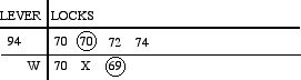
This can be read: Lever 94 Reverse locks 70 Normal or Reverse, 72 Normal, and 74 Normal. Lever 94 Reverse when 70 is Normal locks 69 Reverse.
Locking Sheet for Tower U
Locking Sheet for Tower A (section 1)
Locking Sheet for Tower A (section 2)
Locking Sheet for Tower A (section 3)
Locking Sheet for Tower A (section 4)
Locking Sheet for Tower C
Locking Sheet for Tower B (section 1)
Locking Sheet for Tower B (section 2)
Locking Sheet for Tower B (section 3)
Locking Sheet for Tower B (section 4)
List of changes in Grand Central locking (1913–1956)
My main GCT page